Saturday, December 31, 2011

New Gafiltefuzz Schematic

My first post on this blog was a schematic of a simple fuzz circuit I like to call the Gafiltefuzz due to it's filtery sound. Well, I tweaked it some and built it up earlier this week and it sounds great. There are some problems, which I will discuss in an upcoming video demo of it. In the meantime, here is the schematic for it so you can build it up yourself and maybe solve the problems with it:


For the meantime, ignore the 9V's with the pot going to ground. This was going to be the dying battery simulator, but obviously that is the wrong way to do it. I don't know why it's drawn that way. . .I really don't.

Thursday, December 22, 2011

Modding A Boss DS-1

A week or so ago, I got a package in the mail, it was from my friend Al, from the band Cannibal Papaya. A couple months ago on facebook I asked if anyone had any guitar pedals they wanted to sell for cheap, and Al being the cool guy he is, sent me this Boss DS-1 for free.

When I got the pedal, the first thing I remembered was the gated feedback mod I saw on Casperelectronics' website, so I decided I'd install that.


This mod is extremely easy, and you only need three things: the DS-1, an SPST toggle switch, and a 2N3904 NPN transistor.

The point of this mod is to add some cool feedback to the distortion without having it squealing when you're not playing anything.


I had these laying around from a couple failed projects, that's why they're not in the prettiest of shape, but who cares? 


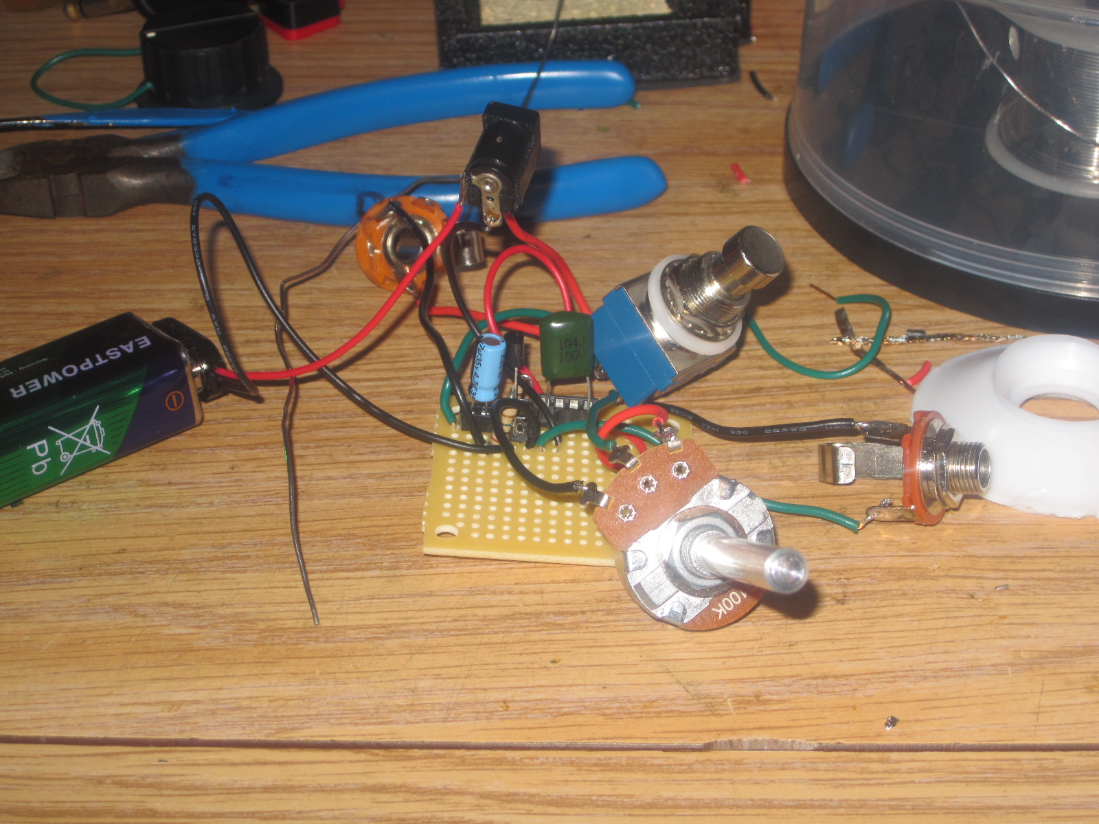
Here's how you should be hooking up your transistor, and remember to throw the switch on the collector.

And here's the whole thing soldered up:


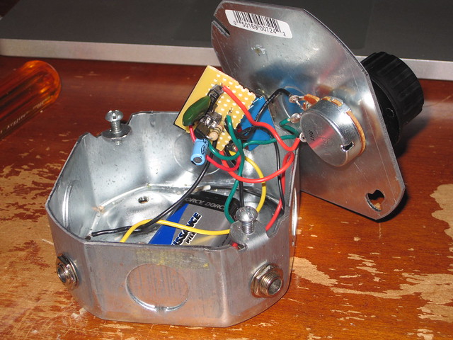
Thankfully there's plenty of space inside the DS-1 to mount the switch on the back side.
To make sure the transistor doesn't short anything out, wrap that S.O.B. in electrical tape or heat shrink tubing. Then you can feel safe cramming it all into the pedal.
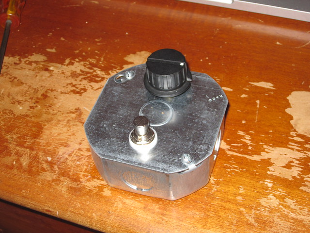
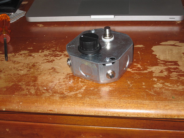
Like A Glove.
And there you have it. A nicely modded DS-1. The end result is a nice bassey feedback effect. It's not something that I'll be using all the time, but for some weird experimentation, it'll work just fine. If I'm feeling more ambitious, I think I'll add a 1/4" jack instead of the toggle switch, so I can add an external foot switch to turn the effect on and off.

Now that I've added this neat effect, I think I better fix that dim dull LED Boss put in this thing.


Friday, December 16, 2011

Rehoused Bazz Fuss

I needed a metal case to cut down on the hum, so I went to True Value and got a electrical device box for a couple bucks.


Monday, November 14, 2011

How To Set Up A 3PDT Footswitch For True Bypass

When I first started messing around with guitar pedals, I could never really figure out how to set up a 3PDT foot switch. I'd never used them, so it was kind of confusing, but when you just think about them as 3 separate SPDT switches it's very easy. I made this little diagram of how to hook it up:

Friday, November 11, 2011

Resistive Bending Probe

Every circuit bender/hacker out there knows the old bending probe of an alligator clip with a couple of jeweler's screwdrivers clipped on, but the resistance of that is incredibly low. The one I'm using here is 0.1Ω.

This low of a resistance can damage the circuit you're modding.

So how can we fix this?

Simple, all we have to do is add a resistor to the cable. Now we don't want a huge resistive load on the cable so I chose to use a 220Ω resistor.


All you have to do is cut the alligator cable in half and solder in the resistor.


I soldered the resistor in so it doesn't make the cable that much larger. If you leave the resistor leads too long it won't be as flexible.

Now all you have to do is add some heat shrink tubing or electrical tape to protect your fancy shmancy new bending probe and you're done. Now you have a 220Ω bending probe that will help prevent any damage to your circuit.


Saturday, October 22, 2011

Bazz Fuss

The Bazz Fuss is an incredibly simple fuzz effect for bass (though can be used with guitar as well). It only uses a handful of parts and you can put it together on your breadboard in about a minute. I would have done this as another "episode" of It Came From Radio Shack!!! but there are a couple more things you can't get there (metal case and 3PDT switch), the actual components though, you can find at Radio Shack. I got mine there for just less than $20.


Parts List (* Not available at Radio Shacks)
2n3904 NPN Transistor
0.1uF Capacitor (Poly-Film)
4.7uF Capacitor (Electrolytic)
100kΩ Resistor
100kΩ Potentiometer
1N914 Diode
Rubber Feet
Protoboard
Knobs
Metal Case*
3PDT True Bypass Footswitch*


All together, these things cost about $35.

I'm basing my build on this schematic from Home-Wrecker.com:


The circuit is insanely easy to build and can be thrown on a breadboard in less than a minute. Here's what mine looks like on the breadboard.

I also added a 1MΩ resistor for a little voltage divider to get it to work on mine. If you have a problem with your circuit working, just try adding that.

After testing it out on the breadboard for a bit, it was time to solder it up. I decided to use sockets for the caps and transistor, since there are many substitutions for these parts that add their own flair to the circuit.

The finished circuit.
The original enclosure I was going to use was too small and I could not fit the battery in, so until I can get another one (I'll probably order it next week), I'm using a crappy little plastic box I grabbed at Radio Shack a little while back. Here's the final product all boxed up.


Sunday, October 9, 2011

It Came From Radio Shack!!! #1 - Line Mixer


Welcome to my new portion of the blog, It Came From Radio Shack!!!. Being the paranoid type, I tend to not want to order parts online for my personal projects. So I occasionally (constantly actually) peruse the component bins at the Radio Shack in the mall. I've build many projects from the parts I get there, and I thought I'd share them with you.

As a circuit bender, I need a little mixer for recording and playing live, but I really don't need all the fancy shmancy functions of the one's I see online. So I found this schematic online and thought I'll modify it for the easily accessible parts I can find at Radio Shack. The modifications are replacing the TLO72 dual op-amp with a TLO82 dual op-amp (which are virtually the same IC), the 2.2uF cap at C7 is now a 10uF, and the 8.2kΩ resistor limiting the current to the LED is now a 220Ω.


Sorry this doesn't have a real step by step process. I finished the project before I thought of this ongoing article. For my next project (still figuring that one out) I'll take pictures of the entire project, from breadboarding to laying out the enclosure.


DISCLAIMER:
This mixer is perfect for mixing different bent devices, but if your bent device has an extremely hot (loud) output, put a volume lowering resistor in line with the jack. If the output is too loud it will bypass the volume control in the mixer and be very very loud. I learned about this from plugging my speak and spell into it and having it be louder than toys that were cranked up all the way even when the S&S was turned all the way down (on all tracks). If you want to know how to adjust the volume of your bent toys, check out this article by Casperelectronics.


Next time on It Came From Radio Shack!!!: Resistor Box

Wednesday, August 31, 2011

New Project Coming Soon

Picked this up last night. I know there are build plans on them on websites like Casperelectronics.com and many others, but I think I'm going to do a step by step tutorial on bending one. I tried one years ago when I was new to bending and I killed it within moments of cracking it open. I hope to God that it doesn't happen again.

I know the casing to these ones are really fragile, so I'll probably end up rehousing it, and I know there are a lot of purists out there who hate rehoused bent devices, and I feel for you, but I gotta do what I gotta do.

Anyway, I'll be uploading pictures and other goodies when this project gets going, so stay tuned.

Also, as you probably noticed, I've been neglecting this blog for a couple months, this is because I have another site, www.dylanpalme.co.nr, that I'm selling my bent goodies and homebrew synths from. So head over there and if anything catches your fancy, get in contact.

 A closer look at the board.


Update 9.6.2011:

I added a 20K pot (okay, it's a 10K with a 10K resistor on the middle lug) for pitch. It's attached to the 15K resistor right under the black blob IC. I completely replaced the 15K for this mod to get the full extent of the bend.

I know there are feedback bends, but I may not do those for this. I'm planning this as a guitar pedal, so I'll probably hold off on any bends that are too noisy.

More updates and documentation soon.

Tuesday, July 12, 2011

555 Keyboard is finished!!

Been working on this since last week. You can see all the technical stuff in the previous post. Here's a  picture of it in its new enclosure:

The three controls are pitch (left), filter (center), and LFO rate (right). It's an 8 key monophonic keyboard. The highest note is the one that plays. A video will be coming soon, if you like it and would want one built for you, get in touch. Email me here: dylanpalme@heofthehouse.com

Thursday, July 7, 2011

555 Keyboard

I've been planning this doo-hickey for a while now, and this morning I finally started it. It's nothing too special, just an 8 note keyboard built from a bastardized optical theremin. I added 8 N.O. pushbuttons with 4.7K resistors in between. They're wired in series which makes this thing monophonic. Here's the heart of the circuit all soldered up:


I still have a little bit of work to do on this. I'm adding a vactrol and an LM324 filter. I'll upload video and photos of everything when it's all done, so stay tuned to this blog.

Update 7-9-2011:
Have yet to add the filter or vactrol, but the damn thing died on me somehow trying to cram it into the case. Updates on this may be lacking due to the fact that I might have to build the entire thing over again. Damn.

Update a few hours later:
It's alive! It's aliiive!!

Update 7-11-2011:
Still kickin'. Installed the LM324 filter, and it sounds amazing. Not what I was expecting it to sound like (different from when I prototyped it, hmmm), but I think it sounds better. Right now it's housed in a small alarm clock case, but since I need more room, I'm transferring the circuits into a sturdier (and bigger) project box.

 I still need to add the LFO/Vactrol to the circuit. I'll end up doing that mess tomorrow. After that, all I need to do is put everything in the new enclosure and presto, it'll be done. Videos and photos will be posted tomorrow I hope.  


Tuesday, June 7, 2011

Mint Tin Microphone

Well, kind of. I made this out of a Sucret's lozenge tin. A LM386 simple amp circuit (you can find the schematic in the datasheet here I used the "Amplifier With Gain" schematic) wired up with a speaker for the input and a 1/4" jack for the output. It makes you sound like a carnival barker.

The only modifications I made to the schematic was to use a .1uf cap instead of a .05uf, and a 100uf instead of the 250uf cap. I also bypassed the 10K pot and just have the input going straight to pin 3.

Here's some pictures of my circuit:


It's a bit cramped, but it's a small circuit for a small tin so it's okay. So the circuit doesn't short out on the metal tin, I smeared some silicon goop on the bottom on of the board.


I also used this silicon goo to hold the speaker in place.


It's not the prettiest sounding mic, but it works.

Finished Project:


A bit cramped inside.


Listen here:
Microphone by Dylan Palme

Monday, May 23, 2011

TL082 Filter

Been messing with this thing all day. It's a very simple Highpass (sounds like one to me but what do I know?) Filter built around a TL082 Dual Op-Amp IC. It doesn't sound too bad (sound sample coming soon), but there is one problem: I can only run one or two things through it. Only a crappy 555 synth and a 555 opto-theremin work with this filter (and the theremin barely works through it). I was wondering if the kind folks out there in the internet could possibly help me out and let me know what the heck I'm doing wrong.

Here's the schematic:

Wednesday, May 18, 2011

Gafilterfuzz

I've been messing with this guitar pedal for a long long long long time. Not because it's an insanely complex circuit, just because I've been lazy. It's really simple, and really fun. It's based off an LM324 quad op amp chip and random parts I had laying around.

Parts:
(1) LM324
(1) 100K Pot
(1) 10K Pot
(1) 4.7K Resistor


And obviously you need the standard 3PDT switch, in/out jacks, 9V battery clip/AC Jack and that kind of junk.

Schematic:


It's a little iffy. From my testing, when the battery is low, you don't get much fuzz from it. Build it, share it, have fun with it. If you have any mods, post them in the comments.

Listen to it here:
Fuzz Demo by GuyIncognito